Website owner: James Miller
Electromagnetic induction. Emf induced in a moving conductor. Faraday’s law. Lenz’s law. Self-induction. Self-induced emf. Self-inductance of a coil of n turns. Energy stored in an inductor. Electrical oscillations. Electric generator, motor.

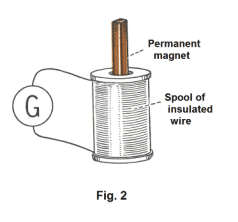
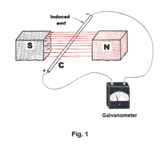
Electromagnetic induction. A great milestone occurred when Hans Christian Oersted discovered in 1819 a connection between electricity and magnetism in the form of a magnetic field near a current-carrying wire. Another great milestone occurred 12 years later in 1831 when Michael Faraday discovered another phenomenon relating electricity and magnetism: He discovered a phenomenon called electromagnetic induction. This discovery made possible a method for the generation of large amounts of electricity by mechanical means in the form of the electric generator --- which then ushered in a great revolution in our way of living in the form of our age of electricity. Let us learn more about this phenomenon that he discovered. Let us connect a conducting rod C to a sensitive galvanometer, as shown in Fig. 1, and pass the rod down between the poles of a horseshoe magnet. When we do this, a deflection of the galvanometer needle occurs, indicating a current. What a remarkable phenomenon! Who would expect such a thing?! When the rod is held stationary in the field, no current flows. Current only flows when the rod is moving within the magnetic field. When the rod is moved upward within the field, current flows in the opposite direction from which it flows when the rod is moved down. In addition, we discover that the faster the rod is passed through the field, the greater is the deflection of the needle. Thus moving the rod quickly through the field gives a greater current. Let us move the rod laterally between the poles, parallel to the flux lines. No current flows when we do this. Current only flows when we cut across flux lines. Let us consider another experiment. Let us connect a galvanometer to a spool of insulated wire as shown in Fig. 2 and plunge a bar magnet down inside the hole in the spool. Again, the galvanometer needle deflects, indicating a current. When the magnet is withdrawn, the galvanometer indicates a current in the opposite direction. The faster it is plunged down, the stronger is the current produced. When the flux lines of the magnet cross the wire in the coils, current is produced.
When a conductor cuts through lines of magnetic flux or when the magnetic flux field changes in strength around a conductor, an emf is generated (induced) in the conductor. This emf is called an induced emf. If the conductor forms part of a circuit, as in the above cases where it is connected to a galvanometer, that emf produces a current. The current is called an induced current. The phenomenon we are talking about is called electromagnetic induction.
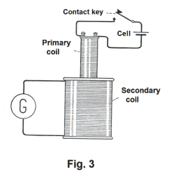
Let us consider another experiment. In Fig. 3 a large wooden spool wound with a large number of turns of fine, insulated wire is connected to a galvanometer. A small spool wound with a few turns of insulated wire is connected in series with a dry cell and a contact key. Let us put the small spool down inside the large spool and press the contact key, closing the circuit. The galvanometer needle will be deflected, showing that a current has been induced in the large coil. What has happened? When we closed the switch and current started flowing in the small coil, that current caused a magnetic field to develop around it, and that developing magnetic field induced an emf and current in the large coil. If the key is kept closed, the induced current in the large coil soon stops. When the circuit is broken, the strength of the magnetic field quickly falls to zero and an induced current flowing in the opposite direction occurs. In both cases the induced current stops flowing when the magnetic field stops changing.
What we have just described represents a way of using one current to produce another. The small coil which is connected to an external power source is called the primary coil. The large coil in which an induced current is produced is called the secondary coil.
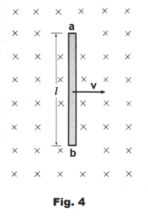
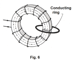
Why is an emf generated in a moving conductor in a magnetic field? What is the cause of this phenomenon that we have just observed? Why is an emf generated in a conductor when it cuts through flux lines in a magnetic field? The answer to that question goes back to another magnetic phenomenon that we have already discussed, namely: When a moving charge cuts through the flux lines of a magnetic field, it experiences a force given by F = qv×B. To see what occurs, consider Fig. 4 where the crosses represent a flux field B directed away from the reader. When conducting bar ab is moving to the right with velocity v, then every charge within the bar is moving to the right, cutting past flux lines, with a velocity v. The consequence of this is that a force of F = qv×B is exerted on every charge within the bar — where the direction of the vector F is along the bar, directed from b to a. This force amounts to an emf within the bar, tending to produce a current from b to a. If the bar is part of a circuit, or connected to a galvanometer as in Fig. 1 above, that emf will cause a current to flow. If the bar is not part of a circuit, then what will happen is that the free electrons in the bar will all move toward end b, making end b negative and end a positive.
Emf induced in a moving conductor. The emf induced in a straight conductor of length l moving with velocity v perpendicular to a magnetic field B is
1) E = Blv
where B, l and v are mutually perpendicular. The emf is in volts when B is in webers/m2, l is in meters, and v is in m/sec.
If the velocity vector v makes an angle θ with the direction of the magnetic field, 1) becomes
2) E = Blv sin θ
___________________________________________________________________
Prove. The emf induced in a straight conductor of length l moving with velocity v perpendicular to a magnetic field B is
E = Blv
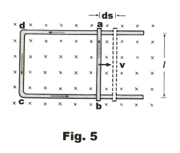
Proof. By definition, E = dW/dq. That is, the emf is the work done on the circulating charge per unit charge (coulomb) displaced past a point of the circuit. Let us consider Fig. 5 in which a moving conductor ab of length l slides along a stationary U-shaped conductor, where the loop is in a plane perpendicular to a magnetic field B. If conductor ab moves to the right at a velocity v, a current I will flow in the loop adcb. Remembering that a magnetic field exerts a force of F = lIB on a long, straight current-carrying conductor perpendicular to the field, we note that the current I moving through the moving conductor ab will cause a side-thrust to the left on ab of
F = lIB
Because of this side-thrust, an external force provided by some working agent is required to maintain the motion. The work done by this agent is the work done on the circulating charge. There is a direct conversion here of mechanical energy to electrical energy.
The distance moved in time t is
ds = vdt
and the work done is
dW = Fds = lIB∙vdt
Now the product of I and dt is the charge dq displaced in this time, so
dW = Blvdq
or
dW/dq = Blv
Since E = dW/dq,
E = Blv
___________________________________________________________________
Faraday’s law of electromagnetic induction. The electromotive force E induced in each turn of wire in any circuit containing loops (as a coil) is related to the time rate of change of the magnetic flux Φ through it by

In the case of a coil of n turns (solenoid or toroid), an emf is induced in each turn, and since the turns are in series, the total emf is

Example 1. Let us consider the circuit of Fig. 5 again. When the conductor ab moves to the right a distance ds, the cross-sectional area of the closed circuit abcd increases by
dA = lds
and the change in the magnetic flux through the area bounded by the circuit is
dΦ = BdA = lBds
If we divide both sides of this equation by dt, we obtain
![]()
or
![]()
which agrees with 3) except for sign. The reason for the difference in sign has to do with sign conventions that need to be employed in regard to direction of current flow, flux direction, etc. i.e. eq. 3) above holds, given the proper sign conventions.
Example 2. Consider the toroidal winding of Fig. 6 linked with a conducting ring as shown. Suppose we set up a magnetic field in the toroidal winding and then vary the field by varying the current in the windings. We know that all of the magnetic flux is confined inside the winding. Thus the conducting ring is not only not moving in a magnetic field, it does not even lie in a magnetic field. Yet experiment will show that if we vary the current in the windings, an emf is produced in the ring.
This shows that an emf can be produced in a conductor even if the conductor does not lie in a magnetic field.
Direction of induced current. Lenz’s law. The induced current flows in such a direction as to oppose, by its electromagnetic action, the motion or cause producing it.
We earlier gave an example of how an induced current can be produced by plunging a bar magnet down into the coil connected to a galvanometer shown in Fig. 2. If the north pole of the magnet is pushed down into the coil, the induced current that is produced in the coil will flow in such a direction as to create a north pole at the top of the coil so as to oppose the action. The two north poles repel each other and work is required to push the pole into the coil. Once the bar magnet has been pushed down into the coil and we attempt to pull it out, the current is reversed and a south pole is formed that attracts the north pole and opposes the action of pulling it out.
In the same way, if we attempt to push the south pole of the magnet down into the coil, the top of the coil will develop a south pole, to oppose the action. From this we see that the energy of the induced current that is produced in electromagnetic induction does not come free. It comes from work that is done. A transformation of mechanical energy into electrical energy is involved in the phenomenon.
If the induced current in a coil is caused by an increase in flux through the coil, the induced current is in such a direction as to set up magnetic lines that are in the opposite direction to the lines of the original field. If a moving wire cuts magnetic flux, the induced current is in such a direction as to set up a magnetic field that opposes the motion.
Self-induction. Suppose we connect a small lamp in series with a switch and dry cell. When we close the switch, the lamp lights up immediately. When we open the switch, the lamp goes out immediately. Now let us put a coil (such as the one shown in Fig. 2) into the circuit. Now when we close the switch, we find that the lamp does not light up so quickly. When we open the switch, the lamp stays lighted longer and grows dim before it goes out. The explanation for this behavior lies in a phenomenon called self-induction, a phenomenon discovered by the American physicist, Joseph Henry (1797 - 1878). In our experiment, the coil slowed the buildup of the current when we closed the switch and then slowed the dying out of the current when we opened the switch. Why did this happen? It happened because of a counter emf, an opposing emf, that occurred in the coil that slowed the buildup and dying out of the current. Where would this counter emf come from? Why would it occur? The answer is that it is a self-induced emf, an emf arising from its own changing magnetic field accompanying its current buildup or die-out. Above, using a primary coil and secondary coil, we showed how a current in a primary coil could induce a current in a secondary coil. When the primary circuit was closed and its current was building up, its developing magnetic field caused an induced emf and induced current in the secondary coil. Well, an increasing current in a coil causes a magnetic field buildup that induces a second opposing emf in the coil itself. By Lenz’s law, this second induced emf will oppose the action of the first emf. The law of electromagnetic induction states that an emf is induced in any circuit in which the magnetic flux is changing. A changing magnetic field around a conductor will cause an induced emf in the conductor. The source of that magnetic field doesn’t matter. It can be from the conductor itself. Consequently, any circuit in which there is a varying current has induced in it an emf because of the variation of its own magnetic field.
The self-induced emf is proportional to the time rate of change of current. The self-induced emf E of a circuit is proportional to the time rate of change of the current I in the circuit

where L is a constant called the self-inductance of the circuit. The negative sign indicates that the self-induced emf is a back emf that opposes the change of current that produces it.
When E is in volts and dI/dt is in amp/sec, L is in henrys. The self-inductance of a circuit is 1 henry if an emf of 1 volt is induced in it when the current changes at the rate of 1 amp/sec.
The self-inductance L of a circuit depends on the size, shape, number of turns, etc. of the circuit. It also depends on the magnetic properties of any materials in which magnetic fields exist. The self-inductance of a solenoid of given dimensions is much greater if it has an iron core than if it is in vacuum.

Def. Inductor. A circuit or part of a circuit that has inductance.
The schematic symbol for an inductor is shown in Fig. 7.
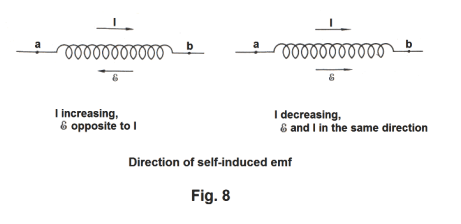
Direction of a self-induced emf. The direction of a self-induced emf is found from Lenz’s law. The cause of the emf is an increasing or decreasing current. If the current is increasing, the direction of the induced emf is opposite to that of the current. If the current is decreasing, the direction of the emf is the same as that of the current. See Fig. 8. It is the change in current, not the current itself, that is opposed by the induced emf.
Self-inductance of a coil of n turns. The self-inductance L of a coil of n turns (solenoid or toroid) is given by
![]()
where Φ is the flux in the coil and I is the current. The quantity nΦ is called the flux linkage of the coil. The self-inductance L is thus the flux linkage per ampere.
Derivation. By Faraday’s law of electromagnetic induction, E = n(dΦ/dt). From 5), E = -L(dI/dt). Thus, L(dI/dt) = n(dΦ/dt), LdI = ndΦ and L = (nΦ)/I.
If a solenoid of n turns has a core permeability μ, length l and cross-section area A, its self-inductance is given by

Derivation. Φ = BA, B = (μnI)/l, and

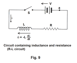
Growth and decay of a current in a circuit containing inductance and resistance. When the switch is closed on a circuit containing inductance, the current will not rise to its final steady state value immediately due to the back emf of the inductance, but will grow at a rate that depends on the inductance and resistance of the circuit. Given a series circuit consisting of a battery of emf V, a resistanceless inductor L and a noninductive resistor R as shown in Fig. 9, the current i at time t is given by
![]()
where Is is the steady state current given by Is = V/R and the switch closing occurs at time t = 0.
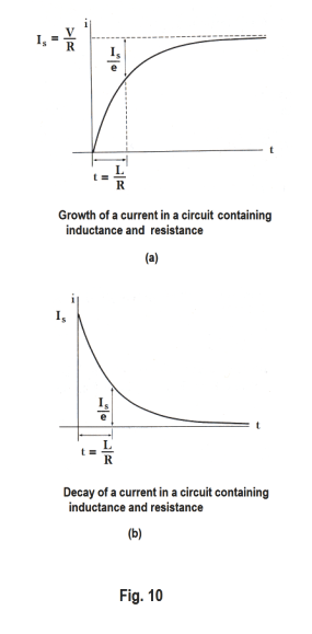
A graph of this equation is shown in Fig. 10 (a). The current rises rapidly and then more slowly, approaching asymptotically the final value Is = V/R.
Time constant. The time constant of the circuit is defined as the time at which Rt/L =1, or when
![]()
When t =L/R, the current i is around 63% of its final value Is. For a circuit with a given resistance, the time required to reach this value is longer the larger the inductance.
Formula for a decaying current. If there is a steady current Is in the circuit of Fig. 9 and the switch is opened, the decay of the current is shown in Fig. 10(b). It is the exact inverse of Fig. 10(a). The formula for the decay is
![]()
The time constant L/R is the time for the current to decrease to 1/e of its original value.
Energy stored in an inductor. The energy stored in an inductor (solenoid, toroid, etc.) when there is a steady state current in it is
![]()
Mutual inductance. When a current in a primary circuit (e.g. a primary coil) is changing, an emf is induced in a neighboring secondary circuit (or secondary coil) which is interlinked by any part of the primary flux. The induced secondary emf E2 is proportional to the time rate of change of the primary current, dI1/dt
![]()
where M is a constant called the mutual inductance of the system. If E is in volts and dI1/dt is in amp/sec, M is in henrys.
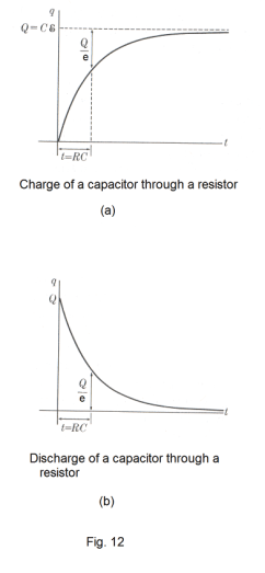
Charge and discharge of a capacitor through a resistor. When the switch is closed on a circuit containing capacitance and resistance, the charge on the capacitor does not reach its final value immediately, but approaches this value in the same way as does the current in a circuit containing inductance and resistance.
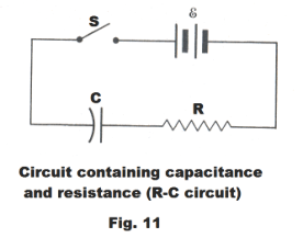
In the circuit of Fig. 11 containing resistance R, capacitance C and a source of emf E, let q represent the charge on the capacitor at a certain instant after the switch S is closed, and let i be the current in the circuit at that instant. Then the amount of charge on the capacitor at some subsequent time t is given by
![]()
where Q = C E.
A graph of the equation is shown in Fig. 12(a). The time constant of the circuit is equal to RC.
Formula for discharge. If the capacitor is originally charged and then discharged through a resistance R, the charge decreases with time according to
![]()
The graph is shown in Fig. 12(b).
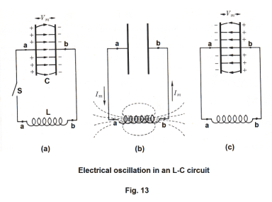
Electrical oscillations in an L-C circuit. Fig. 13 (a) shows a circuit containing a charged capacitor C, an inductor L of negligible resistance, and a switch S. We now consider the oscillatory behavior that occurs when the capacitor discharges on the closure of the switch. At the instant the switch is closed, the capacitor starts discharging through the inductor. As it discharges, a magnetic field builds up in the inductor and the stored up energy of the capacitor is transferred to the inductor. When it has completely discharged, the potential difference between its terminals has decreased to zero. See Fig. 13 (b). The magnetic field of the inductor now starts decreasing, inducing an emf in the inductor in the same direction as the current. The current consequently persists, but with diminishing magnitude, until the magnetic field has disappeared and the capacitor has been charged in the opposite sense to its original polarity, as shown in Fig. 13 (c). The process now repeats itself in the opposite direction and in the absence of energy losses the charges on the capacitor will surge back and forth indefinitely.
The frequency of the electrical oscillations of a circuit containing inductance and capacitance only can be calculated in exactly the same way as the frequency of oscillation of a body of mass m suspended on a spring of force constant k. The frequency of the oscillation of the body on a spring is
![]()
and the frequency of the electrical oscillations is

This frequency is called the natural frequency of the L-C circuit.
In this problem and in many
problems in physics there is a strong
parallelism between
mechanical systems, acoustical systems and electrical systems in that different problems reduce to the same set of differential equations and the solutions are the same except for the meanings of the variables. Because of this parallelism, it is sometimes possible to solve a complicated mechanical or acoustical problem by setting up analogous electrical circuits and measuring currents and voltages which correspond to the desired mechanical and acoustical unknowns.
From the energy standpoint, the oscillations of the above L-C circuit consist of a transfer of energy back and forth from the electric field of the capacitor to the magnetic field of the inductor, with the total energy associated with the circuit remaining constant; a phenomenon analogous to the transfer of energy in an oscillating mechanical system from kinetic to potential and vice versa.
The energy of the capacitor at any instant is ½ (q2/C) and that of the inductor is ½ Li2. Consequently,

where q an i are the instantaneous, and Q and I are the maximum charge and current, respectively.
The effect of resistance in an oscillatory circuit is to drain away the energy of the circuit and convert it to heat. Thus resistance plays the same role in an electrical circuit as friction does in a mechanical system.
Alternating current and direct current. A current that flows in one direction during part of a cycle and in the opposite direction during the rest of the cycle is called alternating current. Alternating current is the type of current usually furnished by power companies. When a current flows in one direction only, it is called direct current. This is the type of current furnished by dry cells and storage batteries.
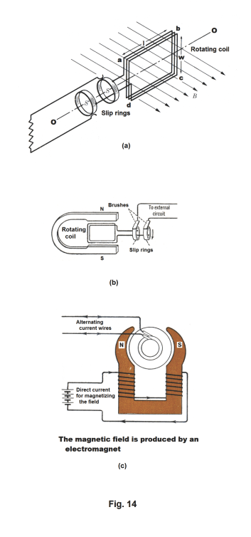
Alternating current generator. The basic operating principle of the alternating current generator is shown in Fig. 14(a). A closely wound rectangular coil abcd of n turns rotates about an axis OO which is perpendicular to a uniform magnetic field of flux density B. As ab and cd of the coil abcd cut through the lines of magnetic flux, electric current is produced in accordance with equation 2) above
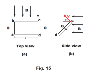
17) E = Blv sin θ
where l is the length of ab (or cd) and θ is the angle that the velocity vector v of bc makes with the flux field B. See Fig. 15 (b). The coil is wound on an iron cylinder called an armature (The assembly of coil plus cylinder is also called the armature). The method by which the electric current from the coil is passed to the external circuit is through slip rings and brushes as shown in Fig. 14 (b). The terminals of the coil are soldered to brass slip rings and brushes consisting of metal strips or carbon blocks rest lightly on the slip rings as they revolve.
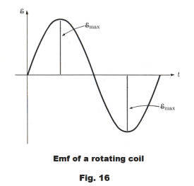
Emf of a rotating coil. The emf of a rotating coil is given by
18) E = Emax sin 2πft
where
19) Emax = nBAω
and
Emax — maximum emf
n ---- number of turns in the coil
B — magnetic field intensity
A — area of the one loop or turn of the coil [A = lw in Fig. 14 (a)]
ω — rate of rotation of coil (radians/sec)
f — frequency of the revolution (revolutions per second)
A graph of 18) is shown in Fig. 16.
_______________________________________________________________________
Derivation of formula. From Fig. 15 (b) we see that the velocity v of bc (corresponding to the velocity of point c) is related to the rate of rotation ω by
![]()
Thus 17) becomes
21) E = ½ Blωw sin θ
which represents the emf generated by a single wire of length l cutting through the flux field B. Since both bc and ad generate emf and since there are n turns, 21) becomes
22) E = nBlωw sin θ
The area A of the loop is given by A = lw, so 22) can be written
23) E = nBAω sin θ
It is easily shown that 23) applies to a coil of any shape, rotating about an axis perpendicular to a uniform magnetic field.
The emf is a maximum when the plane of the coil is parallel to the field and is zero when it is perpendicular to the field. The maximum emf is given by
24) Emax = nBAω
Thus 23) can be written
25) E = Emax sin θ
If ω is constant,
26) θ = ωt or θ = 2πft
and
27) E = Emax sin ωt = Emax sin 2πft
_______________________________________________________________________
The magneto. The simplest type of alternating current generator is one which uses a permanent magnet to produce the magnetic field. See Fig. 14 (b). This type of electric generator is called a magneto. Magnetos are used to supply the alternating current for spark plugs in lawnmowers, motorbikes, outboard motors, and in some airplanes.
Commercial alternating current generators. Using permanent magnets limits the amount of electrical power that can be produced. An electromagnet can produce a much stronger field than can a permanent magnet. Thus commercial AC generators use electromagnets to produce the magnetic field.
The commercial alternating current generator has three essential parts:
(1) Field electromagnets that produce the magnetic field.
(2) The armature consisting of a large number of coils of insulated wire.
(3) The slip rings and brushes.
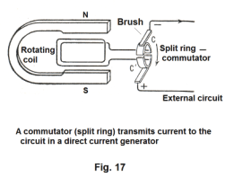
The direct current generator. A direct
current generator differs from the alternating current
generator in only one detail. Instead of using slip
rings to transmit the current from the coils to the
external circuit, it uses a split ring called a
commutator. See Fig. 17. As the coil turns, the
brushes move from one part of the split ring to the other at just the instant when the current
changes direction, thus producing a current that looks
like that shown in Fig. 18 (a). In modern dc
generators the armature consists of many coils
connected in series. Fig. 18 (c) shows the output of a
three coil armature. This armature has two
commutator bars for each coil, for a total of six bars.
They are
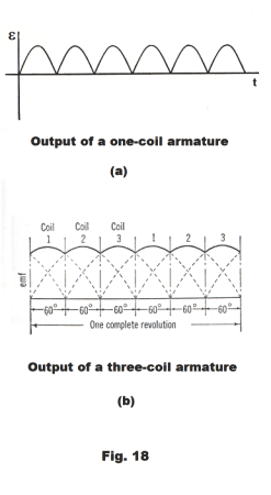
arranged so that each set of bars contacts the brushes during the time that the corresponding coil is passing through the greatest number of lines of flux. Thus coil 1 in the figure supplies its output to the brushes for the first 60 degrees of rotation. It is then cut out of the circuit and coil 2 supplies the output for the next 60 degrees, etc. The emf produced by coil 1 after it has been cut out is shown in the figure by dashed lines. By using many coils, one can obtain a fairly constant output voltage.
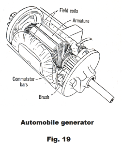
A cutaway view of an automobile generator is shown in Fig. 19.
The electric motor. The basic operating principle of the electric motor is based on one simple fact: a current-carrying wire in a magnetic field will experience a side thrust from the field. As a consequence, a current-carrying loop in a magnetic field will experience a torque. An electric motor is really just a dc generator working in reverse. In the dc generator, the coil is turned through some mechanical means, such as gas turbine, and electricity is produced. If, however, one feeds electricity to the generator it will cause the coil to rotate. If one feeds electricity to the dc generator shown in Fig. 17, the coil will rotate.
Two kinds of direct current motors. Direct current motors may be shunt-wound or series-wound. In a shunt-wound motor, the windings of the field magnet and those of the armature are connected in parallel, whereas in a series-wound motor they are connected in series. The two types have different performance characteristics. A shunt-wound motor has the advantage that its speed is not affected much by varying loads whereas the speed of a series-bound motor is. On the other hand, the torque of a series-wound motor is much greater at starting than that of a shunt motor. A series motor is used when the motor must start under a heavy load.
Series motors may run on alternating as well as on direct current. The current reverses at the same time in both the field and the armature. Series motors are used for fans, sewing machines, vacuum cleaners, etc.
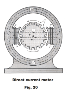
A schematic diagram of a direct current motor is shown in Fig. 20. The armature A is a cylinder of soft steel mounted on a shaft so it can rotate and containing longitudinal slots in which are embedded copper conductors C. Current is channeled into and out of these conductors through graphite brushes making contact with a segmented cylinder on the shaft called the commutator.
The current in the field coils F, F sets up a magnetic field that is essentially radial in the gap between them and the armature. The motor frame M, M provides a path for the magnetic field
Back emf of a motor. The coil of a motor rotates in a magnetic field and consequently produces an emf which, by Lenz’s law, is opposed to the impressed emf. It is called the back emf. The effective voltage that drives the motor is equal to the difference between the impressed emf and the back emf. Thus when running, every motor is also a generator.
The back emf of a motor that is running without a load will be almost equal to the impressed emf. Only enough current flows through the motor to overcome friction. Under a load, the back emf falls and more current flows through the armature to handle the load.
References
1. Sears, Zemansky. University Physics
2. Semat, Katz. Physics.
3. Dull, Metcalfe, Brooks. Modern Physics.
Jesus Christ and His Teachings
Way of enlightenment, wisdom, and understanding
America, a corrupt, depraved, shameless country
On integrity and the lack of it
The test of a person's Christianity is what he is
Ninety five percent of the problems that most people have come from personal foolishness
Liberalism, socialism and the modern welfare state
The desire to harm, a motivation for conduct
On Self-sufficient Country Living, Homesteading
Topically Arranged Proverbs, Precepts, Quotations. Common Sayings. Poor Richard's Almanac.
Theory on the Formation of Character
People are like radio tuners --- they pick out and listen to one wavelength and ignore the rest
Cause of Character Traits --- According to Aristotle
We are what we eat --- living under the discipline of a diet
Avoiding problems and trouble in life
Role of habit in formation of character
Personal attributes of the true Christian
What determines a person's character?
Love of God and love of virtue are closely united
Intellectual disparities among people and the power in good habits
Tools of Satan. Tactics and Tricks used by the Devil.
The Natural Way -- The Unnatural Way
Wisdom, Reason and Virtue are closely related
Knowledge is one thing, wisdom is another
My views on Christianity in America
The most important thing in life is understanding
We are all examples --- for good or for bad
Television --- spiritual poison
The Prime Mover that decides "What We Are"
Where do our outlooks, attitudes and values come from?
Sin is serious business. The punishment for it is real. Hell is real.
Self-imposed discipline and regimentation
Achieving happiness in life --- a matter of the right strategies
Self-control, self-restraint, self-discipline basic to so much in life