Website owner: James Miller
Alternating current. Impedance. Inductive and capacitive reactance. Vector impedance diagram. Phase angles for circuits with pure resistance, pure inductance, and pure capacitance. Resonance. Power in ac circuits. The transformer.
Period and frequency. The period T of an alternating emf or current is the time required for the emf or current to go through one complete cycle. The frequency f of an alternating emf or current is the number of cycles made per second.

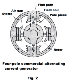
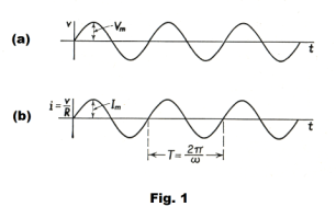
Emf produced by an alternating current generator. A coil of wire, rotating with a constant angular velocity in a uniform magnetic field, develops a sinusoidal alternating emf as represented pictorially in Fig. 1 (a). A schematic diagram of a commercial alternating current generator (or alternator) is shown in Fig. 2. A number of pairs of poles are spaced around the inner circumference of a stator as shown. The rotor (or armature), a cylinder of soft steel, rotates inside the stator on a shaft. On the surface of the rotor, conductors run longitudinally. As each conductor sweeps across the magnetic field, an emf is introduced in it, in one direction as it passes a north pole and in the other direction as it passes a south pole. Thus an alternating sinusoidal emf is produced, the number of complete cycles generated in each revolution being equal to the number of pairs of poles. Hence a four pole generator of the type shown would generate two cycles per revolution. The multipolar structure enables the generator to produce a sufficiently high frequency without an unduly high angular velocity of the rotor. The emf produced between the terminals of the generator is given by
1) v = Vm sin 2πft
where v is the instantaneous potential difference, Vm is the maximum potential difference, and f is the frequency, in cycles per second, of the emf produced.
The frequency f is equal to the number of revolutions per second of the rotor multiplied by the number of pairs of poles of the stator. The product 2πf is called the angular frequency and denoted by ω. For a simple two-pole generator, ω is equal to the angular velocity of the rotor in radians /sec. The frequency produced by most power generators in this country is 60 cycles/sec.
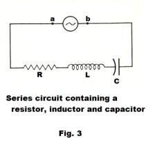
Alternating current in an L-R-C circuit. Consider a series circuit consisting of a resistor, inductor, and capacitor connected to the terminals of an alternator as shown in Fig. 3. We desire the expression for the instantaneous steady-state current i that will flow in this circuit.
The instantaneous potential difference between the terminals a and b is given by
2) v = Vm sin ωt
This potential difference is equal to the sum of the potential differences across the R, L and C elements. Thus
![]()
where q is the charge on the capacitor. Differentiating this equation with respect to t, and replacing dq/dt with i, gives

This is a differential equation of the second order. The solution to the equation consists of two parts: an expression for a steady-state current and an expression for a transient current. We are only interested in the steady state solution, which is

where

The solution can be verified by calculating di/dt and d2i/dt2 and substituting into the differential equation.
It can be seen from the equation that the steady-state current, like the terminal voltage, varies sinusoidally with time and that the maximum value of the current is

Thus the steady-state current can be written as
6) i = Im sin (ωt - f)
We see that the frequency of the current is the same as that of the voltage, but that the two differ in phase by an angle of f.
We now introduce the following notation:
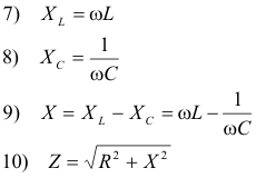
Using this notation

![]()
The quantity Z is called the impedance of the circuit, X is the reactance, and XL and XC are the inductive and capacitive reactance respectively. Impedances and reactances are expressed in ohms. The general term for a device possessing reactance is a reactor.
Thus, for steady-state currents, the maximum current Im is related to the maximum potential difference Vm by
![]()
We note this equation has the same form as Ohm’s law with the impedance Z corresponding to resistance R.
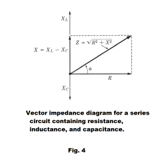
The vector impedance diagram. The relationship between the impedance Z of a series circuit and the values of R, XL, and XC can be presented graphically by treating these quantities as vectors. See Fig. 4. The resistance R is represented by a vector along the positive x axis and the reactances XL and XC are represented by vectors along the positive and negative y axes respectively. The impedance is the vector sum of these three vectors.
Phase angles for circuits with pure resistance, pure inductance, and pure capacitance. The instantaneous voltage and current in an ac circuit is given by
13) v = Vm sin ωt
14) i = Im sin (ωt - f)
![]()
Def. Phase angle. The product ωt in 15) represents an angle (in radians). Its magnitude at any time t is called the phase angle of the voltage. Similarly, the quantity (ωt - f) in 16) is the phase angle of the current.
The angle f represents the difference in phase between the current and voltage. If f is positive,
the current lags the voltage. If f is negative, the current leads the voltage.
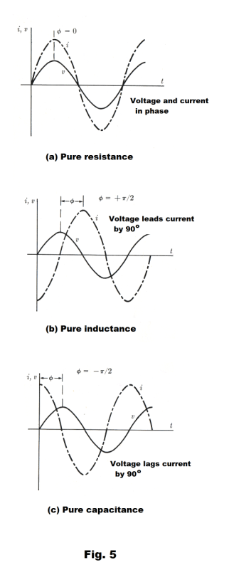
Circuit containing pure resistance. X = 0. Using formula 15), f = 0. The voltage and current are in phase. See Fig. 5 (a).
Circuit containing pure inductance. X = XL. Using 15), f = +π/2. The voltage leads the current by π/2 radians or 90o. See Fig. 5 (b).
Circuit containing pure capacitance. X = - XC. Using 15, f = -π/2. The voltage lags the current by π/2 radians or 90o. See Fig. 5 (c).
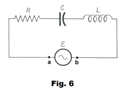
Potential differences across circuit elements in series circuits. Suppose that an alternating current is flowing in a series circuit consisting of an ac generator, resistor R, inductor L, and capacitor C, as shown in Fig. 6. At any instant of time the current must be the same in all parts of the circuit. If the current varies according to
16) i = Im sin ωt
the potential difference across the circuit elements at any instant of time t will be
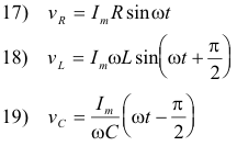
and the potential difference vab across the terminals of the generator at time t will be the sum of these potential differences:
![]()
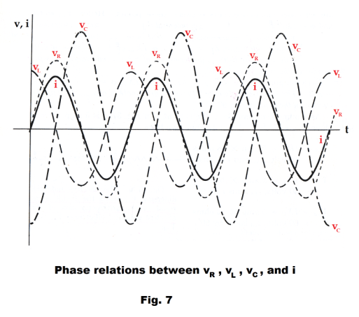
Examine Fig. 7 for insight on how they add up at a particular time t.
Def. Effective, or root-mean square (rms), values of current and voltage in an alternating current circuit. It is more convenient to describe alternating currents and voltages by what is termed their effective, or root-mean-square (rms), values than by their maximum values. The effective value Ieff of an alternating current is defined as that direct current that would develop the same heat in a resistor in the same period of time. Similarly, the effective value Veff of the voltage of an alternating current is that direct current voltage that would develop the same heat in a resistor in the same period of time.
Syn. Effective value, rms value
AC voltmeters and ammeters are calibrated to read effective values.
Theorem 1. The effective value Ieff of an alternating current is given by
![]()
The effective value Veff is the voltage value corresponding to Ieff and is given by
![]()
Effective potential difference between points in an ac circuit. The effective potential difference Vab between any two points a and b in a series circuit is equal to the product of the effective current I and the impedance Zab between the two points, provided there is no seat of emf in the path between the points:
23) Vab = I Zab
where the phase angle between Vab and I is given by

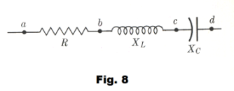
Phase differences occurring in circuit elements containing pure resistance, pure inductance, and pure capacitance. The phase difference between the voltage and current in a circuit element is given by f. Referring to Fig. 8, the value of f between points a and b where there is pure resistance is
f = tan-1 0/R = 0
since Xab = 0. The value of f between points b and c where there is pure inductance is
f = tan-1 XL/0 = π/2
The value of f between points c and d where there is pure capacitance is
f = tan-1 -XC/0 = -π/2
We can thus make the following statements:
1] The voltage between the terminals of a pure resistance is in phase with the current.
2] The voltage between the terminals of a pure inductance leads the current by 90o.
3] The voltage between the terminals of a pure capacitance lags the current by 90o.
We now wish to make an important point: The sum of the effective voltages across a number of circuit elements in series does not equal the effective voltage across the group as a whole. We illustrate this with the following example.
Example. Referring to Fig. 8, let I = 5 amp, R = 8 ohms, XL = 5 ohms, and XC = 11 ohms. Then
Vab = IR = 5 amp × 8 ohms = 40 volts
Vbc = I XL = 5 amp × 5 ohms = 25 volts
Vcd = I XC = 5 amp × 11 ohms = 55 volts
The impedance of the entire circuit is given by
![]()
and the effective voltage Vad across the circuit is
Vad = I Zad = 5 amp × 10 ohms = 50 volts
Thus
Vab + Vbc + Vcd = 40 + 25 + 55 = 120 volts
but Vad = 50 volts.
Resonance in an ac series circuit. A case of great interest is the case where the voltage and current are in phase in an ac series L-R-C circuit (circuit containing resistance, inductance and capacitance). The necessary condition for this situation to occur is that
25) XL = XC
since
![]()
and if XL = XC, then f = 0.
Now
27) XL = ωL = 2πfL
and
28) XC = 1/ωC = 1/2πfC
Equating 27) and 28) gives

from which we get

When this condition is fulfilled, resonance will occur and the current will be a maximum, since impedance will be a minimum. The current will be given by I = V/R since, in this case, Z = R.
Power in ac circuits. Power is the rate at which work is performed or energy is supplied. In the case of direct current, the rate at which a circuit supplies energy to an electrical device is given by
P = VI
where V is the potential difference between the terminals of the device and I is the current flowing through the device. In the case of alternating current, both current and voltage are continually varying and, in general, are not in phase, introducing a complication to the problem. However, the instantaneous rate at which energy is supplied to an electrical device by an ac circuit is given by
P = vi
where v is the instantaneous potential difference between the terminals of the device, i is the
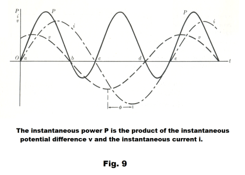
instantaneous current in the device, and P is instantaneous power. Fig. 9 shows graphs of v, i, and the power P where P is computed by multiplying together the values of v and i. Note that in some intervals the power curve is positive (as between a and b) and at other places it is negative (as between b and c). Where the power curve is positive, energy is being supplied to the device, and where it is negative, energy is being returned to the circuit (and being stored in the inductor and capacitor). The total energy supplied to a device over a time t corresponds to the net area under the power curve during that time and the average power is given by the total energy supplied divided by the time.
When one speaks of “the” power supplied to a device in an ac circuit, it is average power that is meant. If the product of v and i is formed to give a power curve and then averaged over a time interval of one period, the average power P is found to be
31) P = VI cos f
where V and I are the effective values of the voltage and current and f is the phase angle between the voltage and the current. The quantity f is called the power factor. Depending on the nature of the device, the power factor can have any value between zero and one. A power factor of zero corresponds to the situation where the device consists of pure reactance, inductive or capacitive.
The transformer. A transformer is a device used to raise or lower voltage in an alternating current circuit. It consists of a primary coil and a secondary coil wound on a common iron core. See Fig. 10. An alternating current in the primary coil sets up an alternating magnetic flux in the core. This alternating flux links with the secondary coil and induces an alternating emf in it.
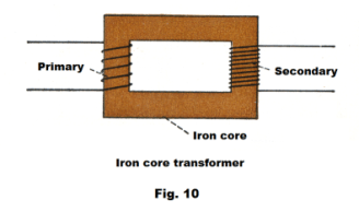
The emf’s in the primary and in the secondary have approximately the same ratio as the number of turns of wire in the coils. Thus if there are 20 turns in the secondary for each turn in the primary, the emf in the secondary will be nearly twenty times as high as the primary. If the primary is connected to a 110 volt ac line, a voltage of around 22,000 volts will be produced in the secondary.
The iron core is constructed of thin iron sheets, or laminations, to minimize heat loss from eddy currents.
A transformer effects a power transfer from the primary coil to the secondary coil. The power output will be less than the power input due to energy losses in the form of heat. Despite losses, the efficiency is usually well above 90%.
Neglecting losses, if E1 is voltage supplied to the primary, E2 is the voltage induced in the secondary, I1 is the current in the primary, I2 is the current in the secondary, N1 is the number of turns in the primary, N2 is the number of turns in the secondary, then
Power in primary = power in secondary
32) E1I1 = E2I2


The main use of transformers is in stepping up voltage for power transmission. Electric power can be transmitted much more efficiently at high voltages than at low voltages due to less I2R heat loss in a high voltage / low current transmission.
Uses of alternating current and direct current. Direct current is used for heating, lighting, electroplating, charging storage batteries, electromagnets, and most other types of electrical work. Its big disadvantage is that there is no practical way to raise its voltage and its voltage cannot be lowered without introducing resistance and wasting power. Alternating current can not be used for electroplating or for any kind of electro-chemical work. It can be used for running motors and for heating and lighting. The big advantage of alternating current is the fact that its voltage can be changed easily using a transformer, and with little loss of energy. Thus it is used for long-distance transmission of electricity.
References
1. Sears, Zemansky. University Physics
2. Semat, Katz. Physics.
3. Dull, Metcalfe, Brooks. Modern Physics.
4. Schaum. College Physics.
Jesus Christ and His Teachings
Way of enlightenment, wisdom, and understanding
America, a corrupt, depraved, shameless country
On integrity and the lack of it
The test of a person's Christianity is what he is
Ninety five percent of the problems that most people have come from personal foolishness
Liberalism, socialism and the modern welfare state
The desire to harm, a motivation for conduct
On Self-sufficient Country Living, Homesteading
Topically Arranged Proverbs, Precepts, Quotations. Common Sayings. Poor Richard's Almanac.
Theory on the Formation of Character
People are like radio tuners --- they pick out and listen to one wavelength and ignore the rest
Cause of Character Traits --- According to Aristotle
We are what we eat --- living under the discipline of a diet
Avoiding problems and trouble in life
Role of habit in formation of character
Personal attributes of the true Christian
What determines a person's character?
Love of God and love of virtue are closely united
Intellectual disparities among people and the power in good habits
Tools of Satan. Tactics and Tricks used by the Devil.
The Natural Way -- The Unnatural Way
Wisdom, Reason and Virtue are closely related
Knowledge is one thing, wisdom is another
My views on Christianity in America
The most important thing in life is understanding
We are all examples --- for good or for bad
Television --- spiritual poison
The Prime Mover that decides "What We Are"
Where do our outlooks, attitudes and values come from?
Sin is serious business. The punishment for it is real. Hell is real.
Self-imposed discipline and regimentation
Achieving happiness in life --- a matter of the right strategies
Self-control, self-restraint, self-discipline basic to so much in life