Website owner: James Miller
Force on a moving charge in a magnetic field. Path of a charged particle in a magnetic field. Force on a long straight conductor. Torque on a coil. Force between two parallel conductors. Galvanoscope, galvanometer, ammeter, voltmeter. Ampere’s law.

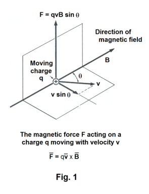
Force on a moving charge in a magnetic field. Ampere discovered that wires carrying current experience a force when placed in a magnetic field. It was later shown that all charged particles moving in a magnetic field experience a force. The force F acting on a charge q moving with velocity v is perpendicular to the directions of both v and B and is given by the following cross product
1) F = qv×B
where F is expressed in newtons, the charge q is expressed in coulombs, the velocity is expressed in meters per second, and the magnetic field intensity B is expressed in webers per square meter. The magnitude of force F is given by
2) F = qvB sin θ
where θ is the angle from v to B. The direction of F is that shown in Fig. 1 when the moving charge is positive and is given by the right hand rule: If you curl the fingers of your right hand in the direction that carries v into B, then your right thumb points in the direction of F.
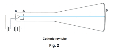
A cathode-ray tube is a convenient device for studying the behavior of a moving charge in a magnetic field. Fig. 2 shows the essential features of a cathode-ray tube. The tube itself is glass and highly evacuated. Electrons (cathode rays) are emitted by a heated filament K and are accelerated toward an anode A which is maintained at a potential of several hundred to several thousand volts above the filament. Most of the electrons are absorbed by the anode, but a narrow wire-like beam passes through a small hole in the anode and continues on to a screen S which is coated on its inner surface with a substance that emits light when struck by electrons.
Let us suppose we have a uniform magnetic field that is directed in the direction of the positive x axis of the xyz coordinate system shown in Fig. 3 (the field might, for example, be that created between the poles of a large electromagnet). Let us now place the cathode-ray tube Q at the origin of the coordinate system, facing in the positive x direction so that its central axis coincides
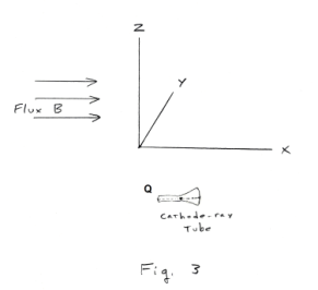
with the x axis. Because the direction of the electron beam is parallel to the direction of the flux, there would be no deflection of the electron beam at this orientation. Now let us suppose we start rotating the cathode-ray tube in a counterclockwise direction about the z axis. As we do so we should see the spot of light on the screen move in a vertical direction as the electron beam is deflected vertically. When we have rotated it 90o so that its axis coincides with the y axis, the amount of deflection will be at its maximum. Here the electron beam is at right angles to the flux B, resulting in maximum deflection. As we continue rotating it the amount of deflection will become less until we reach the angle of rotation of 180o, where the deflection will again be zero. Continuing to rotate it would result in continued vertical deflection.
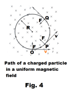
Path of a charged particle in a uniform magnetic field. Sometimes it is desired to represent a magnetic field that is directed either toward the reader or away from the reader. This is usually done with an array of dots or crosses. Dots represent the points of arrows coming toward the reader. Crosses represent the tail feathers of arrows going away from the reader.
The crosses of Fig. 4 represent a uniform magnetic field directed away from the reader. If a charged particle is given an initial velocity v in a direction perpendicular to a uniform magnetic field, it will describe a circular path as shown in the figure. Suppose a positively charged particle located at point O in the figure is given an initial velocity v perpendicular to the field as shown. The field will exert an upward force of F = qvB at point O. Since the force is always at right angles to the velocity, it won’t affect the magnitude of the velocity but will change its direction. When the particle reaches points P and Q the directions of the force and velocity will have changed as shown. We have here a situation in which a constant centripetal force acting on the particle causes the particle to move in a circle in the way a planet orbits the sun. Since

we have, from Newton’s second law,

and the radius of the circular orbit is

where m is the mass of the particle and q is its charge.
If the direction of the initial velocity is not perpendicular to the field, the particle will move in a helix.
The deflection of charged particles by a magnetic field is utilized widely in such devices as the cyclotron, mass spectrometer, cathode-ray tube, etc.
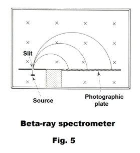
Beta-ray spectrometer. The beta-ray spectrometer is used to measure the velocities of electrons emitted in radioactive disintegrations. Electrons (beta rays) are emitted through a slit into a uniform magnetic field of known strength in a direction perpendicular to the field. The particles are deflected into circular orbits and strike a photographic plate, as shown in Fig. 5. The diameter of the orbit can be measured from the photographic film. From that diameter the momentum mv can be determined and the energy of the particles can be computed.
Force on a current-carrying conductor element in a magnetic field. The force dF, due to a magnetic field B, on a short current-carrying conductor element of length ds making an angle θ with the field is
4) dF = I ds×B
where the direction of the vector ds is that of the current I.
In non-vector form, this is
5) dF = I ds B sin θ
where I is the current in the element..
The force is perpendicular to the plane formed by the current element and the direction of the field.
___________________________________________________________
Derivation. Using eq. 1) above for the force on a moving charge
F = qv×B
we obtain
6) dF = dq v×B
Using the relationship
v dq = I ds
6) becomes
dF = I ds×B
___________________________________________________________
Force on a long straight current-carrying conductor. The force, due to a magnetic field B, on a long straight current-carrying conductor of length L oriented at an angle θ with the field is
7) F = LI×B
where the current I is regarded as a vector. In non-vector form, this is
F = LIB sin θ
where I is the current in the conductor and θ is the angle between the direction of the current and the direction of the field.
Derivation. Eq. 7) follows directly from 5) since B, I and θ are constant.
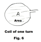
Torque on a current-carrying coil in a magnetic field. The torque L on a coil of n turns carrying a current I in a magnetic field B is
8) L = nBIA sin θ
where A is the area inclosed by a single turn or loop of the coil and θ is the angle between the normal to a single loop and the magnetic field B. See Fig. 6.
The torque is given in meter-newtons when B is in nt/amp-m (webers/m2), I in amp, and A in m2.
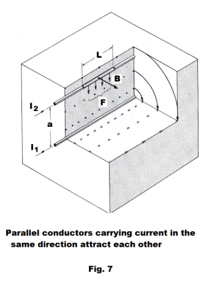
Force between two parallel conductors. When two parallel conductors carry current, there is a force between them that is repulsive when the currents are in opposite directions and attractive when the currents are in the same direction. Since each conductor lies in the magnetic field set up by the other, each experiences a force. The force per unit length, F/L, between two parallel wires carrying currents I1 and I2 respectively is given by
![]()
where a is the distance between the wires and L is the distance over which force F is exerted.
___________________________
Proof. Consider Fig. 7 which shows two conductors carrying current spaced a distance a apart and some of the magnetic flux lines due to the current in the lower conductor. The magnitude of the B-vector at the upper conductor arising from the current in the lower conductor is
![]()
The force on a length L of the upper conductor is given by 7) above:
![]()
or

___________________________
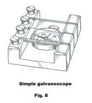
The galvanoscope. A galvanoscope is a device used to detect electric currents using the deflection of a magnetic needle. A simple galvanoscope is shown in Fig. 8. A compass is placed inside loops of current-carrying wire. With a large number of loops, even a feeble current will cause a marked deflection of the needle. The galvanoscope was much used before the invention of the D’Arsonval galvanometer.
The
galvanometer. A
galvanometer
is a device
used to
measure the
strength of a
weak electric
current.
Essentially all
galvanometers used today employ the D’Arsonval movement invented in 1882 by Arsene
D’Arsonval, a French
physician. There are two types of D’Arsonval movement in use: 1) the moving coil type, 2) the pivoted coil type. The original D’Arsonval movement was of the moving coil type.
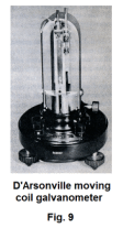
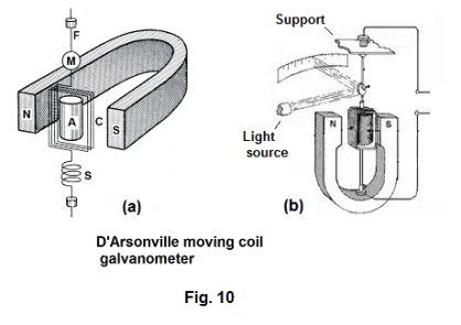
Moving coil type galvanometer. A D’Arsonval moving coil type galvanometer is shown in Fig.
9 and its basic mechanism is shown in Fig. 10 (a) and (b). Referring to Fig. 10 (a), the basic
mechanism consists essentially of a coil C of 10 to 20 turns of insulated copper wire wound
around a rectangular frame and suspended from a fine conducting wire or thin flat strip F
between the poles of a horseshoe magnet. A soft iron cylinder A serves to concentrate the
magnetic flux in the vicinity of the coil. A beam of light strikes mirror M and is reflected to a
scale. See Fig. 10 (b). When a electrical current passes through the coil, a torque L is produced in accordance with eq. 8) above ( L = nBIA sin θ ) and the assembly twists and the amount of twist is read on the scale. A loosely wound spiral S exerts some control on the coil.
The current sensitivity of the galvanometer is defined as the current in the galvanometer coil required to produce a displacement of the reflected beam through one millimeter, on a scale one meter distant from the galvanometer. Typical current sensitivities range from 0.01 microampere to 0.0001 microampere per mm division at one meter.
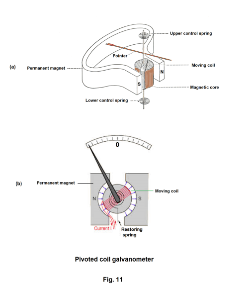
Pivoted coil galvanometer. A pivoted coil galvanometer is a modification of the moving coil galvanometer in which the assembly is pivoted on jeweled bearings instead of being hung from a wire. See Fig. 11. The control springs maintain the pointer at the zero position when no current is flowing. The zero mark is located at the midpoint of the scale. When current flows, the needle will be deflected to the left or right depending on the direction of the current.
The pivoted coil galvanometer has the advantage of being more rugged and portable than the moving coil type. It is not as sensitive as the moving coil type. The smallest currents that can be measured are on the order of magnitude of 0.1 microampere.
A galvanometer is a sensitive instrument for detecting feeble currents of the order of microamperes. A large current will damage it
For the translation of a galvanometer reading into absolute current values, the current sensitivity of the meter must be known.
Def. Current sensitivity. The number of microamperes corresponding to one scale division.
Because the pointer deflection of a galvanometer is proportional to the current passing through the coil, if a current I1 in the coil gives a scale reading of s1, then the current sensitivity is given by Sc = I1/s1.
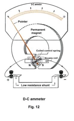
The ammeter. An ammeter is an instrument for measuring currents. It is essentially the basic D’Arsonval movement wired in parallel with a low resistance shunt. See Fig. 12. The bulk of the current goes through the shunt with only a small amount going through the movement. The zero point of the scale is on the left.
Because an ammeter is connected in series in a circuit when taking current readings, it is important for its resistance to be low so as not to reduce the amount of current flowing.
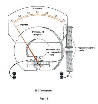
The voltmeter. The voltmeter is an instrument for measuring potential differences. It is essentially the basic D’Arsonval movement wired in series with a high resistance coil. See Fig. 13.
A voltmeter needs to measure the potential difference between two points in a circuit without appreciably changing that potential difference. Since a voltmeter is connected in parallel when making readings, it is important for accurate readings that very little current go through the voltmeter.
We note that a voltmeter is an instrument that measures current flow, just as the ammeter and galvanometer. Because by Ohm’s law, voltage drop V is proportional to current I, one can scale current to voltage drop.
Ampere’s law. Ampere’s law is closely analogous to Gauss’ law. Gauss’ law states a relationship between the surface integral of the normal component of the electric intensity E over a closed surface and the net charge enclosed by the surface. Ampere’s law states a relationship between a line integral summing the tangential component of the magnetic induction B at points along a closed curve and the net current passing through the area bounded by the curve.
Let C be an arbitrary closed curve circling some wires in which current is flowing. The current in the wires creates a magnetic field in the area surrounding them. Ampere’s law states that the line integral ∫B∙ds of the magnetic induction B around curve C is equal to μ0 times the algebraic sum of all the currents ∑I (currents in one direction are considered positive, those in the opposite direction are considered negative) intercepted by the area spanning the path.
Ampere’s law.
![]()
(bold type and over-bar both used to indicate vector) In words, the line integral of the magnetic induction B around any closed path C equals u0 times the current intercepted by the area spanning the path.
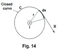
Consider a long straight wire carrying a current I flowing away from the reader and a closed curve C consisting of a circle of radius r centered on the wire and in a plane perpendicular to the wire as shown in Fig. 14. The magnetic induction at a point a distance r from a long straight wire is
![]()
Its direction is tangent to the circle as shown in the figure. The line integral of B around C then is
![]()
Thus in this special case we see that the line integral ∫B∙ds is equal to u0I.
References
1. Sears, Zemansky. University Physics
2. Semat, Katz. Physics.
Jesus Christ and His Teachings
Way of enlightenment, wisdom, and understanding
America, a corrupt, depraved, shameless country
On integrity and the lack of it
The test of a person's Christianity is what he is
Ninety five percent of the problems that most people have come from personal foolishness
Liberalism, socialism and the modern welfare state
The desire to harm, a motivation for conduct
On Self-sufficient Country Living, Homesteading
Topically Arranged Proverbs, Precepts, Quotations. Common Sayings. Poor Richard's Almanac.
Theory on the Formation of Character
People are like radio tuners --- they pick out and listen to one wavelength and ignore the rest
Cause of Character Traits --- According to Aristotle
We are what we eat --- living under the discipline of a diet
Avoiding problems and trouble in life
Role of habit in formation of character
Personal attributes of the true Christian
What determines a person's character?
Love of God and love of virtue are closely united
Intellectual disparities among people and the power in good habits
Tools of Satan. Tactics and Tricks used by the Devil.
The Natural Way -- The Unnatural Way
Wisdom, Reason and Virtue are closely related
Knowledge is one thing, wisdom is another
My views on Christianity in America
The most important thing in life is understanding
We are all examples --- for good or for bad
Television --- spiritual poison
The Prime Mover that decides "What We Are"
Where do our outlooks, attitudes and values come from?
Sin is serious business. The punishment for it is real. Hell is real.
Self-imposed discipline and regimentation
Achieving happiness in life --- a matter of the right strategies
Self-control, self-restraint, self-discipline basic to so much in life